Electrical Schematic Symbols, Electronics Schematic Symbols
We often get requests for electrical schematic symbols and electronic schematic symbols Here we have tried to collect electronic symbols that you might encounter while reading a schematic.so Most experienced engineers know these symbols and rarely need to look it up. If there is any symbol that you encounter and whose meaning you don't understand, please upload it using the form at the end of this page and we will try to explain it.
I think people want these symbols for multiple purposes
* to understand a schematic they are reading * to use in a document they are preparing in Open Office or Microsoft Word
Electrical Schematics Symbols for Open Office and MS Word
Electrical Schematic Symbols in Open Office format
RF Electronics Schematic Symbols in MS Word Format
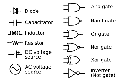
Electrical Schematics Symbols Graphics
Here are some electronics symbols (converted from those available at Wikipedia and Wikimedia)
CAD Tools for drawing Electronics Schematics
If you want to draw a lot of schematics, the best way is to download the open source CAD tool kicad. Kicad runs on Linux too.
Another open source CAD tool is GPL EDA. You are better off using GPL EDA if you run Linux and are comfortable with running command line programs.
If you just want to draw schematics on Windows and export the Netlist, Tiny CAD is a good option
If you think you will be doing a lot of Electrical design you will probably need to get a commercial tool. These tools range from low priced tools like Eagle CAD from cadsoft.de to mid priced tools like Altium to high priced tools like those from Cadence. We presently use Altium.
Use Hardware Description Language?
Drawing a schematic is not really necessary to layout and fabricate a board. The schematic is a convenient way for us to understand the workings of the circuit, but all we really need to build the board is the gerber file. We could use a Hardware Description Language (HDL) to describe the parts and their interconnects. This could then be compiled to a common netlist format and used as an input to PCB layout program. One of these days when I have some time I will write such a compiler.
Schematics DO NOT scale. The reality is that we are able to get away with schematics at the board level is because most boards have a few parts interconnected. All the complexity is there in chips. The chips themselves are for the most part designed using a hardware description language like VHDL or Verilog.
Top of Electrical Schematic Symbols
Need More Help? Have An Opinion?
Do you need more help to solve your problem? Would you like to ask the author a question about your specific problem? Do you have a great idea about this?
We will post an answer within 2 business days. If you need more immediate assistance or you would like to discuss your issue privately, please use our contact us form or call us at 1-888-215-8557. We love solving technical issues and there is no charge if we solve your problem over email or over a short phone call.